 English
 Español
 عربى
Engineered to address the long-term challenges of chemical erosion and structural aging in architect...
READ MORESep 14, 2026
Content
Drainage Channel CAD Details: A Specifier’s Guide to Trench Drain Design
A good drainage channel CAD file does more than save drafting time. It helps the whole project team understand how a trench drain fits into the surrounding paving, when a section needs a heavier grate, and why the invert elevation matters before the concrete is poured.
Every surface water system begins with a simple movement: rain lands on a hard surface, travels to a linear opening, and disappears into a buried pipe. The drainage channel is that linear opening. In CAD terms, it is not a single rectangle dropped into a paving layout. It is a prepared section with a slope, a bedding zone, a grate system, and an outlet connection that has to line up with everything around it.
When someone searches for drainage channel CAD, the first thing they usually want is a prepared drawing. A useful file shows more than the outline of the channel. It should clearly communicate the relationship between the channel body, the grate, the surrounding concrete, and the drainage network.
Before you open the file, take time to review the site condition. A trench drain in a car park behaves differently from a drainage channel in a courtyard. The first is part of the structural pavement; the second is an architectural line in the landscape. If you are still deciding which system is right for your project, this overview of drainage channel systems is a useful starting point.
A complete drainage channel CAD detail should show the following elements without requiring a phone call to the manufacturer:
Good CAD libraries also distinguish between a schematic symbol and a construction detail. A schematic symbol is enough for early layout. The construction drawing has to show the actual product geometry, including edge bars, end caps, and connection to the pipe. When the detail is complete, the contractor can order the right channel body, place the correct grate, and set the outlet without waiting for a clarification.
The most important number on a drainage channel CAD detail is not the channel length. It is the load class. In many markets, channel systems are classified according to EN 1433. The letter and number define the design load that the complete channel system can safely carry.
| Class | Typical application | Design point load |
|---|---|---|
| A 15 | Pedestrian areas, cycle lanes | 15 kN |
| B 125 | Car parks, light vehicle decks | 125 kN |
| C 250 | Kerbs and slow-speed vehicle zones | 250 kN |
| D 400 | Carriageways and hard shoulders | 400 kN |
| E 600 | Industrial yards, freight areas | 600 kN |
| F 900 | Airports, ports, extreme load areas | 900 kN |
Choose the load class from the traffic scenario, not from the brochure. A pedestrian alley and a delivery lane can look the same in plan and behave very differently under a truck wheel.
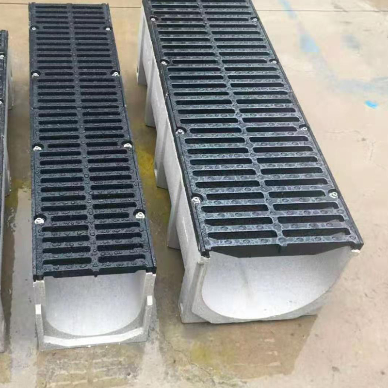
For a pedestrian-oriented project where maintenance vehicles occasionally cross a pavement, the sensible choice is often a channel that has enough structural capacity without changing the appearance of the paving. A low-profile linear channel keeps the detail clean while protecting the finished surface edge.
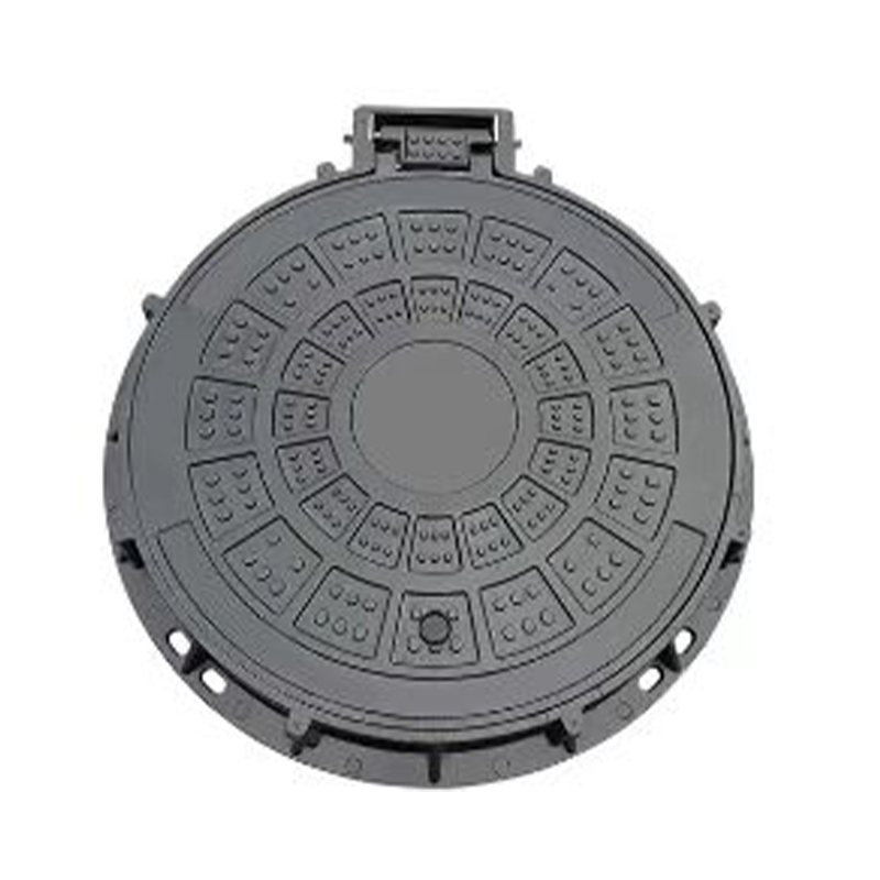
When the design moves to the carriageway, the frame and grate become part of the structural edge. Ductile iron is a common material because it combines stiffness with the ability to transfer load into the concrete surround. For heavy traffic areas, a ductile iron trench grate is often the reference point for the CAD section.
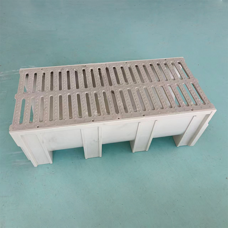
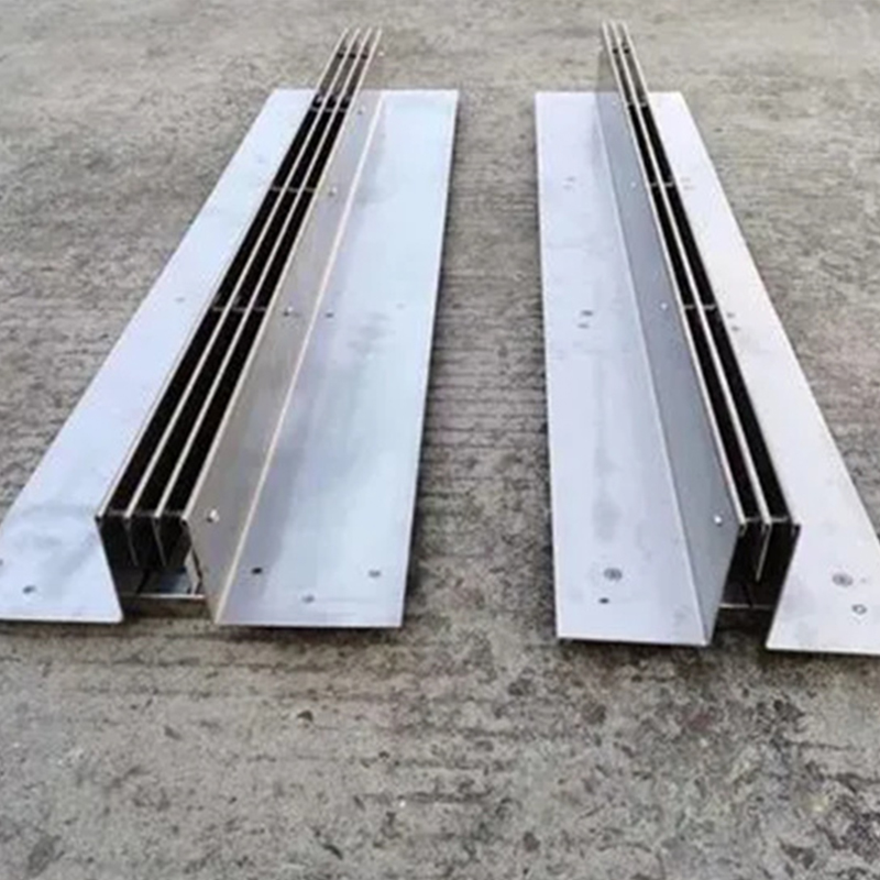
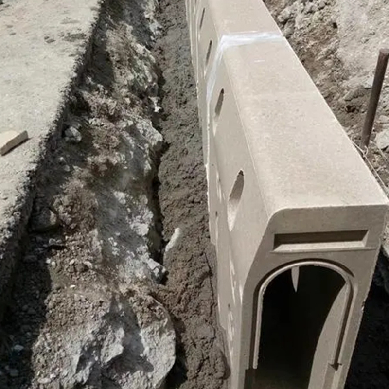
The channel body material affects not only the load class but also how the detail behaves over time. Resin concrete channels are widely used because the material resists corrosion and has a smooth inner surface that helps water move quickly. Stainless steel channels work well in green roofs, planters, and exposed architectural settings where the channel line will be visible. Precast concrete channels suit longer runs where speed of installation matters and the concrete surround can be simplified.
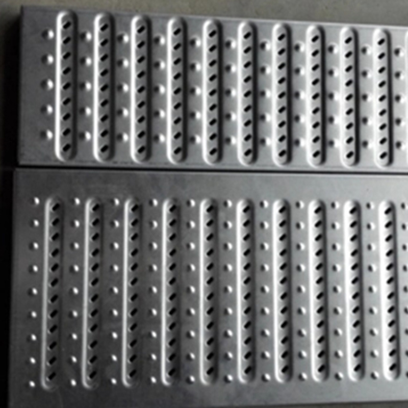
Linear slot drains are narrow, continuous openings that almost disappear into the pavement surface. The grating is often less visible because the slot remains open. A good CAD detail for these units should confirm the slot width and the bearing edges, especially when paving materials are cut to match the channel.
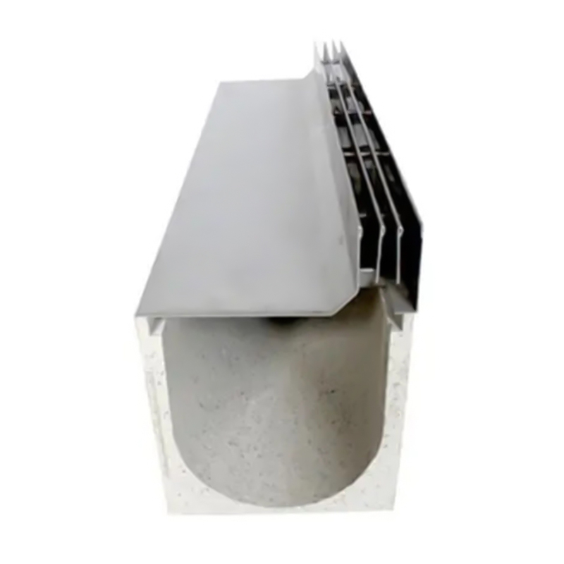
Curb channels combine drainage with the physical edge of the roadway. They are ideal for landscape perimeters, parking islands, and streetscape projects where a separate channel would create an unnecessary joint. A carefully detailed kerbslot can make the drainage line look like a deliberate part of the curb rather than an afterthought.
If the project has a strong landscape component, compare a slotted curbslot unit with a conventional linear drain. The visual width is much smaller than the hydraulic capacity suggests, which is often what the design team needs in tight urban edges.
Most drainage problems do not appear in the first rain. They appear after the first load cycle, or during a delay on site while someone tries to match an unidentified grate. These are the mistakes we see most often when reviewing drawings:
Warning
Check the product data sheet for the combined channel, frame, and grate. A channel body can be D 400 rated, but if the specified grate is only C 250, the full system is no more than a C 250 system.
Coordination with the paving supplier is also critical. The position of the drainage channel against adjacent units determines whether the finished surface can remain flush. If the drawing shows a movement joint too close to the frame, the edge can spall. The CAD file should place movement joints at a sensible distance from the channel body and leave enough room for the concrete surround.
A well-made drainage channel CAD detail should be readable by someone standing on site with a plan and a tape measure. It should show the direction of flow, the outlet bay, and the exact position of the channel against the finished paving level. It should also show how the channel connects to the next component, whether that is a pipe, a gully, or an end cap.
Installation errors are often caused by missing bed heights. A channel placed on compacted sand at the bottom of a trench will move under traffic. The CAD detail should include both the concrete surround and the compacted foundation that supports it.
Success
When the drainage channel CAD detail is coordinated with the pavement build-up, the site team can set the grate level in one pass. That reduces rework and keeps the finished surface flush with the surrounding paving.
When you review a drainage channel CAD file, use the drawing as a conversation piece with the engineer, the landscape architect, and the site team. The geometry and load class are only complete when they are tied to the surrounding material and the drainage network.
Danger
Never let a downloaded symbol replace a specifier’s responsibility. The CAD detail is a starting point. The project conditions, load assumptions, and local regulations define the final product.
Info
A complete drainage channel detail should identify the product series, the material grade, the load class, the width, and the frame type. If any of those five values are missing, the drawing is not ready for tender.
The best drainage channel CAD drawings do more than provide geometry. They translate a manufacturer’s engineering knowledge into a language that the design team and the site team both understand. Start with a verified detail, check the load class and material, and keep the installation sequence in mind. That process will save hours of drafting time and prevent the small failures that usually appear only after the pavement is finished.
Related Products
Engineered to address the long-term challenges of chemical erosion and structural aging in architect...
READ MOREEngineered to address the long-term challenges of chemical erosion and structural aging in architect...
READ MOREEngineered to address the long-term challenges of chemical erosion and structural aging in architect...
READ MOREEngineered to address the long-term challenges of chemical erosion and structural aging in architect...
READ MOREEngineered to address the long-term challenges of chemical erosion and structural aging in architect...
READ MOREEngineered to address the long-term challenges of chemical erosion and structural aging in architect...
READ MORE
Contact us
Factory Address
Group 12, Quanxin Village, Donghai Town, Qidong City, Nantong City, Jiangsu Province, China
phone
+86-13914963840
+86-13451754670
products
QR CODE
 Wholesale Drainage Ditch Manufacturers