 English
 Español
 عربى
Energy-Efficient Sustainable GRC Curtain Wall Panels are high-performance architectural panels desig...
READ MORESep 27, 2026
Content
Drainage channel CAD details look deceptively simple. A plan, a section, a few dimensions — it can seem like the most straightforward drawing on the tender package. Yet in practice, the linear drain is one of the most failure-prone elements in external works, and most of those failures trace back to information that was either missing or ambiguous in the CAD detail.
Most drainage channel failures are not material failures. They are details that were never defined.
This guide outlines what a drainage channel CAD detail should contain, how to verify the load class and material specification, which installation points matter most, and the warning signs of a drawing that will cause problems later on site.
A complete drainage channel CAD detail has to answer five questions: where the channel runs, how it is sized, what load it can carry, what it is made of, and how it is installed. In drawing terms, those questions translate into three common views:
Manufacturer-specific details add an extra layer of value because the geometry reflects the actual product. Wall thickness, locking mechanisms, outlet positions and the bearing surfaces under the grate are drawn from real product data rather than assumed. That is why many specifiers now request manufacturer CAD details during tender, and why our drainage channel series documentation is organised around verifiable product geometry.
Most drainage channel failures are load failures. The channel sits in the ground, the grate carries the traffic, and if the load class does not match the real traffic on the surface, cracks and settlement follow within months rather than years. When you open a CAD detail, the load class is the first callout to look for. Across Europe and most projects in the Middle East and Asia, EN 124 is the reference standard, and it defines six load classes based on the test load a channel and grate can withstand.
| Class | Test load | Typical applications |
|---|---|---|
| A15 | 15 kN | Pedestrian zones, cycle lanes, private driveways |
| B125 | 125 kN | Sidewalks, car parks, light vehicle access |
| C250 | 250 kN | Road shoulders, slow lanes, roundabouts |
| D400 | 400 kN | Carriageways, loading bays, heavy vehicle access |
| E600 | 600 kN | Industrial yards, docks, container areas |
| F900 | 900 kN | Airports, heavy industrial sites |
The implication is straightforward. If the CAD detail does not specify a load class, the drawing is incomplete. If it specifies a class that does not match the project traffic, the drawing is wrong. For sites with concentrated wheel loads — loading docks, industrial yards, airport aprons — specifying a ductile iron grate on a properly supported channel is usually the safer route.
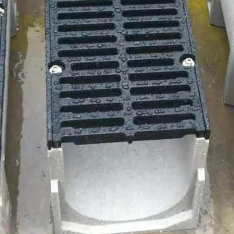 Ductile Iron Heavy Duty Trench Grates for Extreme Wheel LoadsThis grate family supports concentrated wheel loads in demanding sites like docks and airport aprons, with load classes up to F900 and impact toughness suited to heavy traffic.View Product →
Once the load class is verified, the next thing to inspect in a drainage channel CAD detail is the material callout. It affects cost, behaviour in contact with chemicals and standing water, and how well the drain copes with temperature swings and abrasion. Three material families dominate the market.
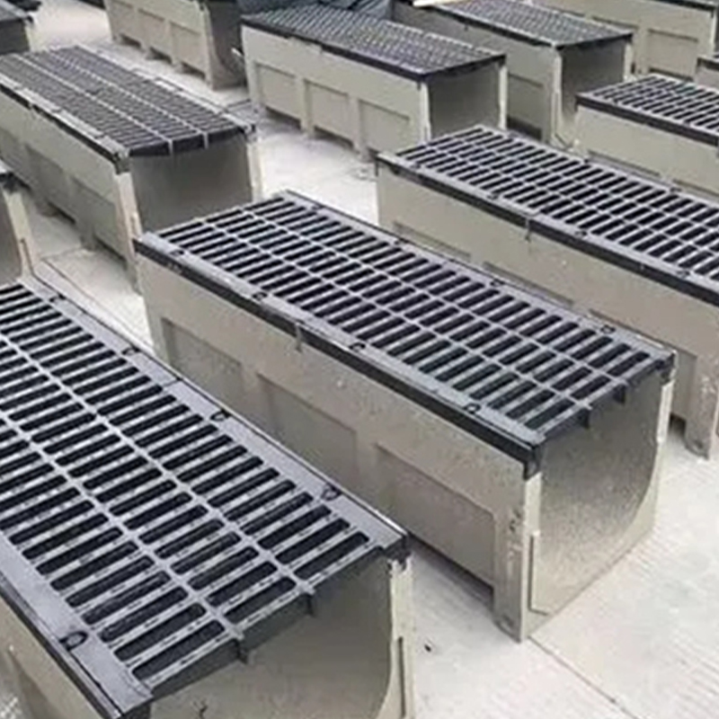
Resin concrete channels are the default for most urban and landscape projects. They are lighter than traditional precast concrete, resistant to aggressive soils and most chemicals, and the smooth internal walls keep water moving even at low flow rates. For projects where runoff carries road salts, mild acids or industrial residues, a corrosion-resistant resin channel balances cost and durability better than most alternatives.
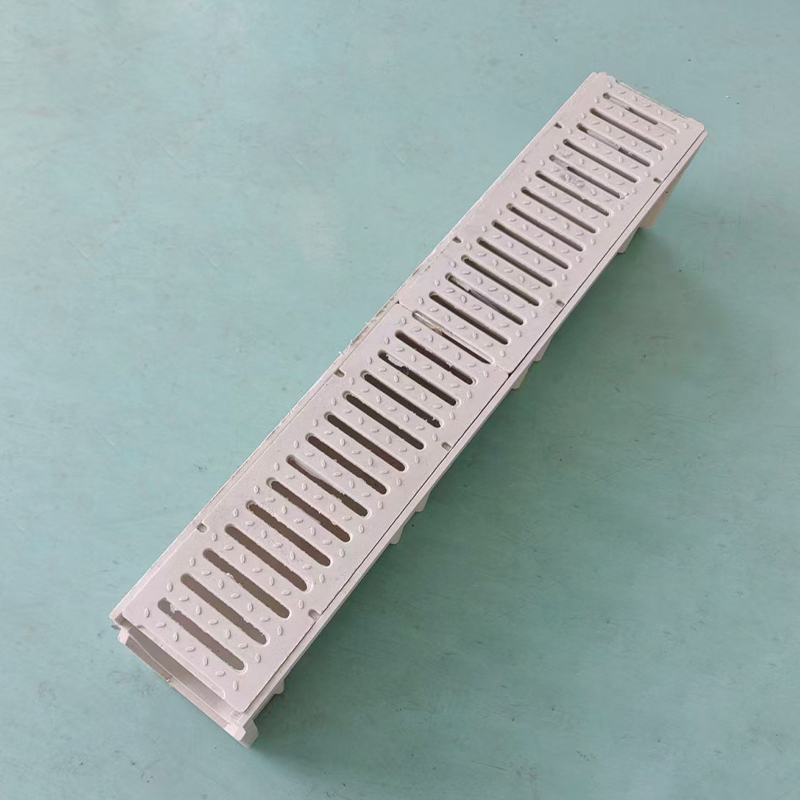 Corrosion-Resistant Resin Concrete Drainage ChannelA lightweight, high-strength channel that resists acids, salts, and industrial residues, making it a practical choice for urban drainage and chemically aggressive environments.View Product →
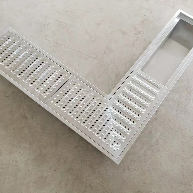
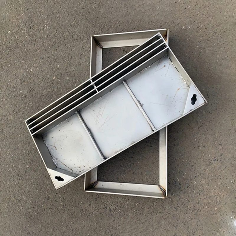
Stainless steel channels and grates are selected where appearance and hygiene drive the decision. They appear in architectural paving, commercial kitchens, shower areas, food-processing plants and public squares. Stainless systems also work well for narrow slot drains, since the slim visible profile disappears into the pavement. In the CAD detail, the stainless grade should always be stated — 304 for most environments, 316 for coastal or chemically aggressive conditions.
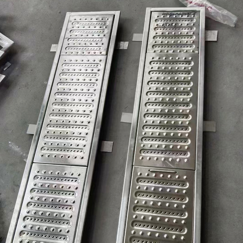 Linear Stainless Steel Drainage Channel for Hygienic SpacesFeaturing an ultra-narrow 10–20mm slot and 304/316 stainless steel, this channel suits architectural paving and food-processing areas while achieving C250–D400 load classes.View Product →
Cast iron and ductile iron grates are the reinforcement for heavily loaded systems. A resin concrete or precast channel with a ductile iron grate handles the heaviest traffic classes while keeping the installation straightforward. Pay attention to the interface between the grate and the channel body: there should be a clear bearing surface and a positive locking mechanism so the grate cannot walk out under traffic.
A good CAD detail makes all of this explicit. It names the resin class, the stainless grade, the cast iron grade and the finish. If the notes say only "material to suit" or "as selected," the detail is not ready for construction.
Channels do not fail in the drawing, but the drawing decides where failure happens. The most common failure points sit at the interface between the channel and the material around it. A well-developed CAD detail draws those interfaces carefully and dimensionally. Five details matter most:
If a detail skips any of these, the contractor will make an assumption. Assumptions on site lead to rework, and rework on buried drainage is always expensive. For a closer look at the practical sequence, our step-by-step channel drainage installation guide covers the same ground from a site perspective.
Having reviewed many drainage channel drawings over the years, a handful of patterns signal that a detail needs to be improved before it is priced or built:
An early conversation prompted by a questionable detail is much cheaper than a site instruction issued after the concrete is poured. If a detail is not clear, ask for the verified, product-specific version. Good manufacturers have it available, because good manufacturers treat the CAD detail as part of the product.
Drainage channel CAD details are where design intent becomes construction reality. The load class tells you whether the system will survive traffic; the material grade tells you whether it will survive the environment; and the installation details tell you whether it will survive the contractor. A drawing that answers all three questions with precision is the cheapest form of insurance on any external drainage project. A drawing that does not is worth challenging — before the concrete, not after.
Related Products
Energy-Efficient Sustainable GRC Curtain Wall Panels are high-performance architectural panels desig...
READ MOREEnergy-Efficient Sustainable GRC Curtain Wall Panels are high-performance architectural panels desig...
READ MOREEnergy-Efficient Sustainable GRC Curtain Wall Panels are high-performance architectural panels desig...
READ MOREEnergy-Efficient Sustainable GRC Curtain Wall Panels are high-performance architectural panels desig...
READ MOREEnergy-Efficient Sustainable GRC Curtain Wall Panels are high-performance architectural panels desig...
READ MOREEnergy-Efficient Sustainable GRC Curtain Wall Panels are high-performance architectural panels desig...
READ MORE
Contact us
Factory Address
Group 12, Quanxin Village, Donghai Town, Qidong City, Nantong City, Jiangsu Province, China
phone
+86-13914963840
+86-13451754670
products
QR CODE
 Wholesale Drainage Ditch Manufacturers